May 4, 2005 One of the annoyances associated
with the Smiths/Jaeger instruments is that the nighttime illumination
is bad. Part of the problem is due to the gauges' design: the
instrument face is lit by reflection from the ring that sits behind the
glass, and the light path from the bulb to the ring is blocked by the
gauges' internals in some cases. Then it doesn't help that the light
bulbs are typically old and will have deposited tungsten onto the
internal surface of the bulb, reducing its brightness. Dirt and rust
inside the case also reduce the brigthness.
So say you've cleaned and repainted the inside of the case and the
reflector ring, replaced the bulb, cleaned the glass, and you're still
not happy with the gauge illumination? You can replace the 2 watt bulb
with a 4 watt halogen bulb... this will definitely increase the
brightness but the resulting increase in heat output inside the
instrument case is not good for its longevity or calibration. I decided
to investigate LED illumination. LEDs have much higher illumination
efficiency than incandescent bulbs, but the downside generally is that
they are fairly directional in nature. LED technology vs. incandescent bulbs
Incandescent bulbs create light simply by passing current through a
high-resistance metal wire, heating it up until it glows. Conventional
tungsten filaments produce a yellowish light. Quartz-halogen bulbs use
an iodine gas to allow the filament to operate at a higher temperature
without evaporating, and this produces a whiter light for the same
electrical power input. The downside, of course, is that the higher
temperature can be destructive towards nearby materials.
LEDs, or light emitting diodes, use a completely different principle to
produce light. A diode is a semiconductor that conducts electricity in
one direction only, and in addition, it creates a voltage drop that is
mostly independent of the amount of current flowing through the device.
In light emitting diodes, the energy absorbed in this voltage drop is
re-radiated as light. Different diode materials give different colours
of light; over the years the availability of colours has increased,
from red, to yellow, to green, and most recently, blue and violet LEDs
have become available. The extension of LED technology to blue and
shorter wavelengths was a fundamental breakthrough, and it allows some
interesting applications to piggyback on this technology. One of them
is that blue and violet light are energetic enough to excite
fluorescent materials, and this is the technology used in "white" LEDs
- a blue/violet LED illuminates a slug of fluorescent material, and the
fluorescent material re-radiates white light. LEDs for gauges
There are commercially available LED bulbs intended for incandescent
bulb replacement. Most of these have a narrow viewing angle that is
coaxial with the bulb base. For the gauges, this is not useful, because
the light path required is actually out to the side. I experimented
with reshaping the lens on a LED bulb, but the results were not very
encouraging. Possibly this would work if the lens was molded in the
correct shape, but the brightness just didn't seem to be there.
Some recent perusing of the Digikey catalog turned up some new parts
from Osram. These LEDs were 2 x 3mm in size, had a relatively broad
illumination field, and good brightness. My thought was that I could
mount six of these behind the bezel ring so that the instrument face
would be illuminated evenly. The downside of this idea was that
mounting would be a little tricky, and while doing this for the
speedometer and the tach would be relatively simple, it would be harder
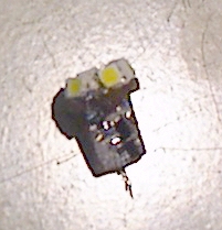
to do this with the other gauges. Then it occurred to me that the LEDs
were small enough to mount in a circular array on a modified bulb base.
I cut a piece of circuit board material to 3/8" diameter and mounted
the six LEDs on there so that they faced slightly upwards relative to
the lamp base. On the backside of that board I mounted another board of
about 1/4" by 5/16", with the current regulator components. White LED
brightness is a function of the supply current, and they can be damaged
by too high a supply voltage, so the inclusion of an internal regulator
circuit was mandatory.
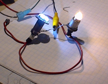
After testing the basic operation I installed the array on an E10 screw
base and compared it to a 2W incandescent bulb.
The array is on the left, the incandescent is on the right. The LED
array is bright enough that it's hard to look at. The 2W light bulb
consumes roughly 160 mA, while the LED array draws only 60 mA.
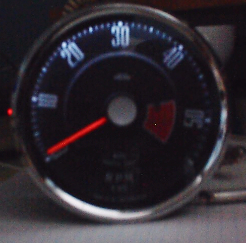
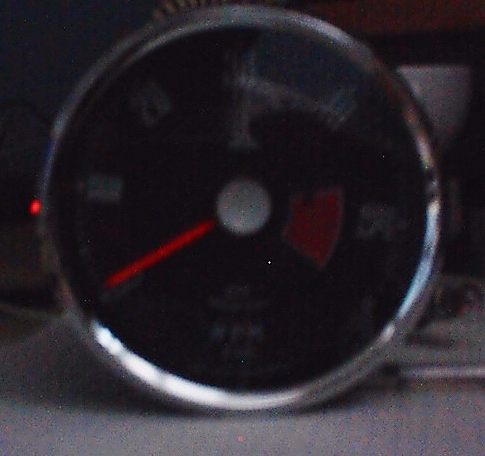
Lastly, here's some pictures of my tach, LEDs on, and off:
Unfortunately, these pictures don't do the overall effect justice.
The illumination toward the right side is poorer due to internal
shadowing in the tach... this can be fixed but only by cutting out
parts of the OEM circuit board. My initial idea of doing the lighting
in a ring around the tach would fix this problem, but it's much more
invasive to install.
Conclusion
This technology works, but it's not cheap. Presently these LEDs cost
just under $2 each in small quantities, and the fabrication time required to
build the boards and assemble the array into the base is not trivial.
However, the improvement in illumination is good enough that I'll
probably build another five or six of these for the rest of my
instruments.