Temperature and Fuel Gauges for Dummies!,
Or,
Everything You Ever Wanted to Know About Temperature and Fuel Gauges, But were Afraid to Ask.

An Article by Stu Brennan
June, 2001
Page 1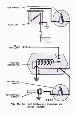
The Sunbeam temperature and fuel gauges are electrical instruments powered by the panel voltage regulator. Each gauge is in series with its sender. See the diagram below, taken from the Workshop Manual.
The interior works of the fuel and temperature gauges are the same, but the numbers on the faces are, of course, different.
Below is a description of each of the components of the system. Following that, is an explanation how it all works together, and how to troubleshoot your problem.
You remember about bimetal strips from High School physics? They have two metals, with different coefficients of thermal expansion, bonded together. When the temperature changes, the strip bends. Well, that’s what our gauges are based on. A heater is wrapped around a bimetal strip, which is fixed at one end, and has the pointer we see on the other. (Actually there are TWO bimetal strips in each gauge, one with the heater, and a second to compensate for ambient temperature.) You have no doubt noticed how the fuel gauge pointer does not snap to it's final positions as soon as you turn the key on. Instead, it drifts up to position over a few seconds. This is the time it takes the heater to heat the bimetal strip in the gauge to the proper temperature. Though seemingly an annoyance, this slow response serves a purpose, which is explained in the regulator section.. The current thorough the heater is controlled by the sender resistance.
Since the gauges are driven by the heaters, it does not matter which way you connect the leads. Current flowing in either direction will produce the same reading. The resistance of the gauge is around 60 Ohms, plus or minus a few Ohms.
CAUTION: DON'T TRY THIS AT HOME: On the face of the gauges are some extra little marks that probably have something to do with their calibration or test procedure. If you open one of the gauges you will see what appears to be some calibration adjustment works. Starting to get some ideas? There’s just one little problem. WE DON'T KNOW WHAT TO DO WITH THE MARKS OR THE ADJUSTMENTS. At exactly what input level do you make each of the adjustments? The factory probably had a procedure involving simulating different input levels and tweaking the adjustments to give the right readings, to wind up with reasonable accuracy over the whole scale. If you don't know the procedure, the sequence of levels and adjustments, you will end up with the "fat lady and the girdle" scenario. Squeeze it in here, but it pops further out over there. I once had great plans to tweak the accuracy of my Smiths voltmeter (a thermal device not unlike our temp and fuel gauges), and then going crazy for a while trying to get it back to useable accuracy. I should have left it alone.
Gauge Calibration Note
'Tiger' Tom Ehrhart Quotation:
"I have previously taken exhaustive accurate measurement of 10 new temperature sensors in a controlled oven, and determined the nominal resistance of this sensor over a wide range of operating temperatures, and statistically determined what the voltage drop at each temp should be. He then used this value to calculate what voltage is required to make a temperature gauge indicate a specific value.
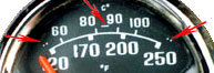 If you look along the outer edge of the gauge face you will see three sets of two dots each at the low, mid and high points. It's the same for fuel or water. Using the data from the new sender units I have calculated that it takes the following voltages applied across the gauge to produce the low, mid, and high indications. They are 2.0 , 4.8, and 7.6 volts respectively. All this is based on using new Smiths senders units. If they were wrong, then we are all in trouble."
Tom Ehrhart
Editors Note: The Fuel gauge has similar markings. While not measured, I'd bet they are the same voltages. A variable DC power supply, with accurate voltage readings, could verify these values on individual units. If anyone has this available, it can be added to this article.
 **
**