Tiger Gauge Information
An Article by Stu Brennan
June, 2001
Page 2
|
|
 |
|
|
Voltage Regulator |
|
|
|
|
|
|
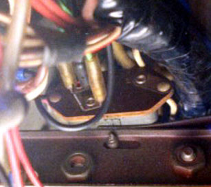
The system voltage in a Tiger, in fact in any car, is not a constant 12 Volts. It can be 14 or 15 Volts during charging, or maybe 11 or 12 Volts when your generator dies.
If the gauges were directly connected to this voltage, their readings would go up and down as the system voltage varied. Instead, the panel voltage regulator provides a constant 10 Volts (Well, sort of, Read on!) to power the gauges. The original regulators work in an unexpected manner, as anyone who has ever tried to measure the voltage can attest.
It is a switching regulator, which works sort of like those blinker bulbs that are common in Christmas tree lights. The regulator contains another electrically heated bimetal strip, this one with a switch contact on the end. When the strip is cool it bends and closes the switch, turning on the heater. When it gets hot enough, it bends and opens the switch, turning off the heat. The strip cools, and the cycle repeats. If the system voltage is higher, the heater gets hotter when it goes on, so it turns off quicker and takes longer to cool off and turn on again, etc.
At any instant, the voltage across the heater is either the system voltage or zero, but if you took an average over time, the average voltage across the heater is about 10V, and it stays fairly constant over a range of system voltages. The voltage across the heater is what is applied to the instruments.
This switching actually happens several times a second. Listen closely, and you can hear it, and if you try to measure the voltage with a fast acting meter, you will see the pointer bouncing all over the place. Some digital meters are totally confused by this. Why aren’t our gauge pointers bouncing all over? In the description of the gauges, I mentioned how the gauges react slowly, taking several seconds to settle on a reading when the key is turned on. The gauges react so slowly that they average out the pulsating signal, producing what appears to be a constant reading.
There is an article on this site, contributed by Cullen Bennett, linked here "How to Calibrate Your Tiger Instruments" which not only reviews the regulator subject in some depth, but offers a design for a solid state instrument voltage regulator. This design is meant to allow each instrument voltage to be separately adjusted, in case the instrument or sensor is not nominal.
The temperature and fuel level senders are both variable resistors that respond to different signals. The fuel sender varies its resistance in relation to the height of fuel in the tank. The temperature sender varies its resistance in relation to the coolant temperature. What is the relationship between the parameter being measured and the sender resistance? ? Below is some data I took around 1978 on the gauges in my Mk IA Tiger (assembled in the fall of ’66.) I used a precision resistance decade box to substitute for the senders, and adjusted the resistance up or down until the gauge stabilized at each temperature.
|
|
|
Fuel Gauge
|
|
Temp Gauge
|
|
|
|
Gallons
|
Ohms
|
|
2
|
145
|
|
4
|
80
|
|
6
|
55
|
|
8
|
38
|
|
11
|
21
|
|
|
Degrees F.
|
Ohms
|
|
140
|
150
|
|
176
|
77
|
|
194
|
57
|
|
212
|
41
|
|
248
|
24
|
|
|
|
|
|
|
|
|
|
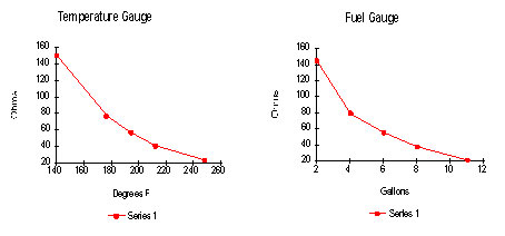
As you can see, higher temperatures, or a full tank, produce lower resistance readings.
 |
|
|
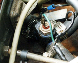
Temp Sender |
|
|
|
|
|
|
Both senders must be attached to ground. The fuel sender is in the gas tank, so its ground is no problem. The stock temperature sender is located in that T in the heater hoses just ahead of the carburetor. There is a wire that grounds this T, and it MUST be intact or the gauge will not move off zero. On the Tiger LAT Manifolds the temperature senders are grounded through the threaded direct connection to the manifold thread mount. This is a special thread size, and is NOT the one that you would find on an Edelbrock F4B made for a US car.
You should be aware that there are many types of temperature senders around, the vast majority of which will NOT match this performance. Countless individuals have discovered this the hard way. Make sure you have the right Lucas sender to match your gauge.
There is an article on this site, contributed by Cullen Bennett, linked here "How to Calibrate Your Tiger Instruments" which not only reviews the regulator subject in some depth, but offers a design for a solid state instrument voltage regulator. This design is meant to allow each instrument voltage to be separately adjusted, in case the instrument or sensor is not nominal.
 **
**