|
Take a reading with the coupling rotating, and the load figure should be as given in the General Data Section. Less than the correct figure will result in excessive deflection of the pinion under load, whilst too much will lead to pitting and failure of the bearings.
To rectify the preload, adjust the shim pack between the outer bearing cone and the pinion shank. Do not touch the shims behind the inner bearing cup, which control the position of the pinion.
Adding shims will decrease preload, removing shims will increase preload.
Installation of the pinion oil seal and slinger is usually effected after fitting the differential assembly.
It must be remembered that, although the measurements and settings must be accurate, the deciding factor of the whole assembly Is the effective tooth marking, and it may be necessary to re-shim the pinion to obtain a correct marking, even though this means an alteration in the cone setting distance.
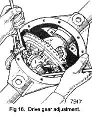
DRIVE GEAR ADJUSTMENT
- Place the differential assembly with the bearing cups and without shims into the housing, being sure that all surfaces are absolutely clean.
- Install a dial Indicator on the housing with the button on the back face of the drive gear (See Fig. 16).
- Insert two small levers between the housing and —bearing cups, and move the differential case and drive gear assembly away from the pinion until the opposite bearing cup is seated against the housing.
- Set the dial indicator to zero, then move the differential assembly towards the pinion drive until the drive gear is deeply in mesh with the pinion. The indicator reading now obtained (clearance be-
|
tween the drive gear and pinion) minus the backlash allowance as etched on the drive gear (e.g. B/L.007) denotes the thickness of shims to be placed between the differential case and the bearing cone on the drive gear side of the differential.
5. Install the thickness of shims determined in the previous paragraph on the drive gear side of the differential, taking the necessary shims from the pack determined previously See “ Differential Bearing Adjustment” on Page 8.
6. Install the balance of the total shims required on the opposite side of the differential case.
As an example of differential and drive gear adjustment assume that the total indicator reading obtained as described under “ Differential Bearing Adjustment” is 08 in. (2.032 mm.). This figure plus .005 in. (. 127mm.) for preload equals 085 in. (2.16 mm.) which denotes the total thickness of shims to be used. Also assuming the clearance between the drive gear and pinion to be .042 in. (1.7 mm.) determined as in operations (1) to (4) as above.
Subtract the backlash as etched on the gear, say -007 in (.178 mm.) from the .042 in. (1.7 mm.) clearance. The .035 In. (.89 mm.) difference denotes the thickness of the shims to be placed between the differential case, and bearing cone on the drive gear side of the differential. Then subtract the thickness of shims .035 in. (.89 mm.) inserted on the drive gear side of the differential case from .085 In. (2.16 mm.) and the difference of .050 In. (1.27 mm.) denotes the thickness of shims to be ins-talled on the opposite side of the case.
Lower the differential assembly into position, lightly tapping the bearing home with a hide mallet, whilst ensuring that the gear teeth are led into mesh with those of the pinion. Careless handling at this stage may result in bruising the gear teeth with subsequent inferior performance from the axle.
Install the differential bearing caps, taking care to ensure that the position of the numerals marked on the gear carrier housing face and the caps correspond.
Remove stretching fixture, or release pressure accord-ing to method used. Finally tighten the bearing cap bolts and torque to the correct figure given in the General data section.
Mount a dial indicator on the gear carrier housing with the button against the back face of the drive gear (as Fig. 16).
|
 **
**