|
GENERAL DESCRIPTION
This model is fitted with a Salisbury axle, of the 4HA type.
The rear axle assembly (Fig. 1) is of the semi-floating type, with shim adjustment for all bearings, meshing of the hypoid drive gear, and pinion matched assembly. The axle shafts are splined at the Inner ends, which engage splines in the differential side gears, while the outer ends have tapers and keys to fit the rear wheel hubs.
The hubs are supported by taper roller bearings pressed on to the axle shafts and located in the ends of the axle tubes. Outward thrust on either wheel is taken by the adjacent hub bearing, whilst inward thrust is trans-mitted through the axle shafts and slotted axle shaft spacer to the opposite bearing.
Thus each hub bearing takes thrust in one direction only. A cover on the rear of the gear carrier housing permits the inspection and flushing of the differential assembly without dismantling the axle.
The gear ratio is stamped on a tag attached to the axle by one of the gear carrier cover screws.
The axle serial number is stamped on the gear carrier housing.
|
AXLE SHAFT – To remove
To remove an axle shaft, the following procedure should be carried out
Remove road wheel and brake drum.
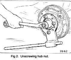
Remove spilt pin from hub and using tool No. RG.1 88-B, unscrew the hub nut.
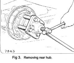
Fit the hub extractor, RG.188-B and RG.188-d-3 and draw off the hub. (See Fig. 3).
Before proceeding further check the end float of the axle shaft with the dial indicator assembly Baty l6O2 (See Fig.5) which should be in. to .008 In. (.15 to .20 mm.). If necessary adjust end float when refitting, by adding or subtracting shims fitted behind ~he backing plate.
At the rear of the backing plate disconnect the hydraulic pipe from the wheel cylinder.
Remove the clevis pin securing the handbrake cable to the operating lever which protrudes from the backing plate.
Remove the brake backing plate retaining bolts, the outer oil seal assembly, the hub bearing retainer plate and the brake backing plate, taking care not to lose or damage any of the hub bearing adjusting shims which control the shaft end float. Refit hub to shaft and fit hub nut.
Withdraw the axle shaft with its taper roller bearing from the axle tube using tool No. RG.188B and RG.16A. as shown in Fig. 4.
|
 **
**