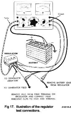
Current limiter test
With the field rheostat at the maximum clockwise position, rotate the centre control to the current regulator position. Continue rotating the control until the voltmeter reading drops to 13 volts. The ammeter will indicate the setting of the current limiter. Remove all test leads except the voltmeter leads. Refit the battery and field leads to the regulator terminals. “Run” the engine at 1500 r.p.m., and read the voltage regulation (under battery lead) on the voltmeter.
Note—The voltage reading will usually be low when the engine is first started, because the battery is partially discharged. After a few moments of operation, the voltage will rise to the original value.
External circuit resistance test:
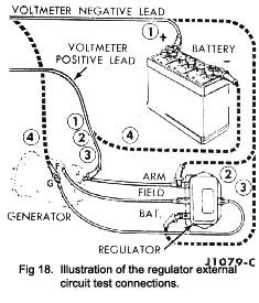
For the purpose of this test, the resistance values of the circuit have been converted to voltage drop readings for a correct flow of 30 amps. Connect the test equipment
|
Illustrated In Fig. 18 to measure voltage drop around the circuit. Crank the engine for 30 seconds with the engine switched OFF to partially discharge the battery. Then, start the engine and ‘ run ‘ it at approximately 1500
r.p.m. Touch the voltmeter negative lead to the centre of the battery positive terminal post as in Fig. 18., to check the generator to battery circuit. The voltage drop should be less than 0.7 volts.
If the voltage drop in the generator to battery circuit exceeds 0.7 volts, locate the exact part of the circuit wiring which is causing the fault, by contacting the volt-meter negative lead to other points of the circuit.
Connect the lead to the armature terminal of the regu-lator, as Indicated in the illustration. The voltage drop should be less than 0.2 volts.
Connect the lead to the battery terminal, as indicated in the illustration. The voltage reading should be less than 0.4 volts.
If the voltage reading is within the limits of the figures quoted, the excessive resistance is in the regulator to battery wiring or their connections.
Check the battery to generator earth circuit by con-necting the voltmeter as Indicated in the illustration (Fig. 18). The voltage reading should be less than 0.1 volts.
|
 **
**