|
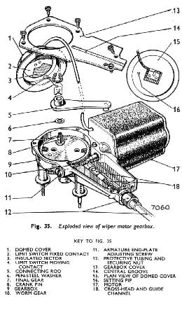
General description (See Fig. 35).
The Lucas windscreen wiper comprises an electric motor and gearbox driving a cable rack mechanism which transmits power to the wheelbox spindles and so to the wiper arms and blades. Rotation of the motor armature Is converted to reciprocating motion in the cable rack by means of a single-stage worm and nylon gear, the motor end of the cable rack being coupled to the crank pin on the gear through a cross-head and connecting rod in the gearbox.
A self-switching feature ensures that the arms and the blades return automatically to the edge of the screen before stopping, irrespective of their positions at the instant of switching off. This is effected by means of a limit switch in the gearbox, its action being controlled by the crankpin. For the greater part of each cycle, the limit switch contacts are closed, providing an alternative earth return path for the motor current. Each time the blades reach the edge of the windscreen at which they are normally parked when the wipers are not being used, the limit switch opens. Thus, when the control switch is OFF, the motor continues to run until the blades reach their parked position.
Maintenance
The gearbox, cable rack and wheelboxes are greased during manufacture and need no periodic lubrication.
Efficient wiping is dependent upon having a clean wInd-screen and wiper blades in good condition. Oil, tar spots or other foreign deposit should be removed from the screen with methylated spirits. Silicone and wax polishes must not be allowed to contaminate the windscreen or the wiper elements.
Worn or perished wiper elements are easily removed for renewal.
|
SERVICING
Failure to operate or poor performance
If the windscreen wiper falls to operate, or gives poor performance, the fault may be either electrical or mech-anical, therefore, to locate the cause, proceed as follows:— Measure the supply voltage
Using a first grade moving-coil voltmeter, measure the voltage between the supply terminal at the motor and a good earthing point, with the control switch ON. For a motor operating normally, this will be approximately 11•5 volts.
|
 **
**