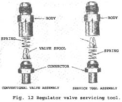
spool seated in the body. This ensures a restricted flow through the regulator valve which is the normal valve function during engine operation at idle speeds.
Identify the service tool as such by painting the engine cubic inch displacement figure on the valve body.
When the regulator valve has been assembled as a service tool, the calibration of the spring may change ; therefore the service tool or its parts should not be used as replacement parts.
2. Disconnect the hose at the regulator valve end and leave the opposite end attached to the intake manifold.
3. Attach the service valve tool to the hose which leads to the intake manifold. Leave the opposite end of the valve vented to the atmosphere.
4. Be sure the crankcase ventilation tube (or hose) fitting at the intake manifold or car-burettor spacer (whichever is applicable) is open.
A clogged orifice in the carburettor spacer or intake manifold will cause the ventilation system to malfunction.
5. Start the engine and compare the engine Idle condition to the prior idle condition. -
If the loping or rough idle condition remains when the regulator valve tool is installed, the crankcase ventilation system is not at fault. Further engine component diagnosis will have to be conducted to find the malfunction.
If the idle condition is found to be satisfactory, refer to page 25 for the cleaning and inspection procedures.
|
Compression test
1. Be sure the crankcase oil is at the proper level. Be sure the battery is fully charged. Operate the engine for a minimum of 30 minutes at 1200 r.p.m. or until the engine is at normal operating tempera-ture. Turn the ignition switch off, then remove ail the spark plugs. Remove the coil high tension lead from the distributor cap and coil.
2. Set the throttle plates and choke plate in the wide open position.
3. Install a compression gauge in No. I cylinder.
4. Using an auxiliary starter switch, crank the engine a minimum of five pumping strokes, and record the highest reading. Note the number of compression strokes required to obtain the highest reading.
5. Repeat the test on each cylinder, cranking the engine the same number of times for each cylinder as was required to obtain the highest reading on the No. I cylinder.
Test conclusions
A variation of 20 p.s.i. from specified pressure is satisfactory. However, the compression of all cylinders should be uniform within 10 p.s.i.
A reading of more than the allowable tolerance above normal indicates excessive deposits in the cylinder or wrong cylinder head(s) on the engine.
A reading of more than the allowable tolerance below normal indicates leakage at the cylinder head gasket, piston rings or valves or wrong cylinder head(s) on the engine.
A low, even compression in two adjacent cylinders indicates a cylinder head gasket leak. This should be checked before condemning the rings or valves.
To determine whether the rings or the valves are at fault, squirt the equivalent of a tablespoon of heavy oil into the combustion chamber. Crank the engine to distribute the oil and repeat the compression test. The oil will temporarily seal leakage past the rings. If approximately the same reading is obtained, the rings are satisfactory, but the valves are leaking. If the com-pression has increased 10 pounds or more over the original reading, there is leakage past the rings.
During a compression test, if the, pressure falls to climb steadily and remains the same during the first two successive strokes, but climbs higher on the succeeding strokes, or fails to climb during the entire test, it indicates a sticking valve.
|
 **
**