Slacken the retaining clip nut and bolt (5) and remove filter holding in an upright position to avoid spilling any oil.
Fit the new filter unit in its location and retighten the retaining clip nut and bolt (5).
Ensure that the joint faces on both the top of the filter unit and the underside of the adaptor (4) are thoroughly clean.
Lubricate the rubber gasket on the joint face of the filter -unit with clean engine oil. Locate the adaptor (4) cen-trally on the filter, and refit the adaptor bolt (2) with its fibre washer (3). Refit the pipe by its union nut (1). After fitting the new filter unit, the engine should be run and the complete filter assembly checked for leaks.
I ON L.H.D. CARS CHECK THAT THE FILTER FLEXIBLE OIL FEED AND RETURN HOSES ARE WELL CLEAR OF THE STEERING UNIVERSAL JOINTS.
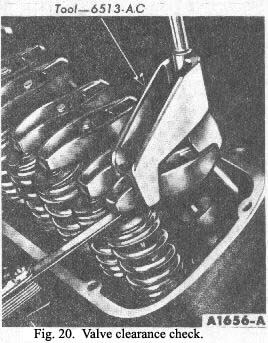
Valve Clearance
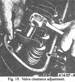
1. Position the crankshaft as outlined in steps 2 and 3. Loosen the rocker arm stud nut until there is end clearance in the push rod, then tighten the nut to just remove all the push rod to rocker arm end clearance. This may be determined by rotating and/ or moving the push rod with the fingers as the stud nut is tightened (Fig. 16). When the push rod end clearance has been eliminated, tighten the stud nut an additional 2 turns to place the hydraulic lifter plunger in the centre of its travel.
|
2. Using an auxiliary starter switch, rotate the crank-shaft until No. 1 piston is on T.D.C. at the end of the compression stroke. With No. 1 piston on T.D.C., adjust the following valves:
| No. 2 Exhaust |
No. 1 Intake |
| No. 5 Exhaust |
No. 1 Exhaust |
| No. 7 Intake |
No. 3 Intake |
| No. 8 Intake |
No. 4 Exhaust |
3. After these valves have been adjusted, rotate the crankshaft 3600 (one revolution) to position No. 6 piston on T.D.C. and adjust the following valves
| No. 2 Intake |
No. 6 Intake |
| No. 3 Exhaust |
No. 6 Exhaust |
| No. 4 Intake |
No. 7 Exhaust |
| No. 5 Intake |
No. 8 Exhaust |
The engine should not be cranked or rotated until the hydraulic lifters have had an opportu-nity to leak down to their normal operating position. The leak-down rate can be accelerated by pressing down on the push rod end of the rocker arm.
The valves can also be adjusted by positioning each piston on T.D.C. at the end of the compression stroke in the firing order sequence
|
 **
**