8. Apply oil-resistant sealer to one side of new cover gaskets. Lay the cemented side of the gaskets in place in the cover(s). Install the valve rocker arms cover(s).
9. Install the Intake manifold and related parts following the procedure under “Intake Manifold Installation.”
VALVE SPRING, RETAINER AND STEM SEAL REPLACEMENT
Broken valve springs, or defective valve stem seals and retainers may be replaced without the need of removing the cylinder head, providing damage to the valve or Valve seat has not occurred.
1. Remove the valve rocker arm cover and the applic-able spark plug.
2. Crank the engine until the applicable piston is on T.D.C. after the compression stroke. Be sure that both valves are closed. Be sure that the piston is on T.D.C. to prevent the crankshaft from turning when the air is applied.
3. Install an air line with an adaptor in the spark plug hole and turn on the air supply.
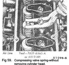
4. Remove the applicable valve rocker arm stud nut, fulcrum seat, valve rocker arm and push rod. Install the stud nut and position the compressor tool as shown In Fig. 49. Compress the valve spring and remove the retainer locks, spring retainer and valve spring.
|
On either cylinder head the rear valve spring cannot be removed with the tool shown in Fig. 49 when the engine is in the car. To remove these springs it is necessary to fit a compressing plate, in place of the rear rocker, and use the adjusting nut to compress and release the valve spring cotters.
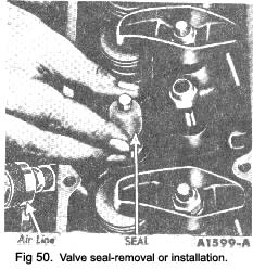
5. Remove and discard the valve stem seal (Fig. 50).
6. Install a new valve stem seal (Fig. 50). Place the spring in position over the valve and install the valve spring retainer. Compress the valve spring and install the valve spring retainer locks. Remove the compressor tool and stud nut.
7. Install the push rod. Apply Lubriplate to the tip of the valve stem and at the push rod guide in the cylinder head.
8. Install the valve rocker arm, fulcrum seat and stud nut. Adjust the valve clearance following the procedure on page 21.
9. Turn off the air and remove the air line and adaptor. Install the spark plug and connect the spark, plug wire.
10. Clean and install the rocker arm cover.
If the right cover was removed install the automatic choke heat tube and the crankcase ventilation regulator valve.
11. Install the air cleaner and Intake duct assembly.
12. Connect the automatic choke heat chamber air inlet hose.
|
 **
**