8. Install the cap and torque the connecting rod nuts to specifications. Do not turn the crankshaft while the Plastigage is in place.
9. Refer to procedure under Main Bearing Replace-ment”
10. After the bearing has been fitted, clean and apply a light coat of engine oil to the journal and bearings. Install the connecting rod cap: Torque the nuts to specifications.
11. Repeat the procedure for the remaining connecting rods that require new bearings.
12. Follow procedure under Main Bearing Replace-ment
MAIN AND CONNECTING ROD BEARINGS
Cleaning
Clean the bearing inserts and caps thoroughly in solvent, and dry with compressed air. Do not scrape gum or varnish deposits from the bearing shells.
Inspection
Inspect each bearing carefully. Bearings that have a scored chipped, or worn surface should be replaced. Typical examples of bearing failures and their causes are shown In Fig. 85. The copper lead bearing base may be visible through the bearing overlay. This does not mean that the bearing is worn. Do not replace the bearing if the bearing clearance is within recommended limits. Check the clearance of bearings that appear to be satis-factory with Plastigage. Fit new bearings following the recommended procedure.
ENGINE MOUNTINGS
Either side mounting bolted to the cylinder block and frame, can be removed from underneath after supporting the engine weight under the sump flange. The engine weight MUST NOT BE SUPPORTED UNDER SUMP. The rear mounting can be removed from underneath by supporting the gearbox weight.
|
ENGINE REMOVAL AND REFITTING
Method
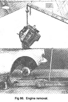
The engine, with gearbox attached, can be lifted out of the bonnet compartment almost vertical, as shown in Fig. 86.
To do this it is necessary to remove the steering unit and raise the front of the car. This gives the room needed to lower the rear end of the gearbox while lifting out the engine unit.
Equipment needed
1. Chain block or garage crane for lifting engine unit.
2. Engine lifting brackets and sling as shown in Fig. 86. These are listed among the special tools
in Section S.
3. Trolley jack for lowering or raising the gearbox weight while the unit is supported on the front lifting gear.
Removal procedure
1. Disconnect battery.
2. Remove bonnet.
3. Drain cooling system, engine sump, also drain gear-box if the gearbox rear end cannot be sealed off,
|
 **
**