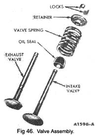
was removed or to which it was fitted. Install a new stem seal on the valve.
2. Install the valve spring over the valve, and then install the spring retainer. Compress the spring and Install the retainer locks (Fig. 35).
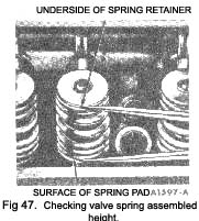
3. Measure the assembled height of the valve spring from the surface of the cylinder head spring pad to the underside of the spring retainer with dividers (Fig. 47). Check the dividers against a scale. If the assembled height is greater than specifications, Install the necessary O.O3O in. thick spacer(s) between the cylinder head spring pad and the valve spring to bring the assembled height to the re-commended height.
|
Do not install the spacers unless necessary. Use of spacers in excess of recommendations will result in overstressing the valve springs and overloading the camshaft lobes which could lead to spring breakage and worn camshaft lobes.
Installation
Before refitting either cylinder head the exhaust manifold must be bolted to the cylinder head, and the rear push rod put into its position in the cylinder head.
1. Clean the cylinder head and cylinder block gasket surfaces. If the cylinder head was removed for a cylinder head gasket replacement, check the flatness of the cylinder head and block gasket surfaces.
2. Position the new cylinder head gasket over the cylinder dowels on the block. Coat the head bolts with water-resistant sealer. Position the cylinder head to the block and install the retaining bolts. Remove the holding fixtures.
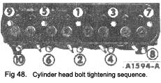
3. The cylinder head bolts are tightened in three progressive steps. Torque all the bolts in sequence (Fig. 48) to 50 ft./lbs., then to 60 ft. lbs., and finally to specification given in the Data Section under Torque Loadings. After the cylinder head bolts have been torqued to specifications, the bolts should not be disturbed.
4. Install the push rods in their original positions. Apply Lubriplate to the valve stem tips and the push rod guides in the cylinder head.
5. Install the rocker arms. Perform a valve clearance adjustment as outlined on page 21.
6. Position a new gasket(s) on the muffler inlet pipe(s). Connect the exhaust manifold(s) at the muffler Inlet pipe(s). Torque the nuts to specifications.
7. Position the generator and bracket and position the drive belt over the pulley, install the retaining bolts and adjust the drive belt tension as explained on page 20. Connect the generator wires.
|
 **
**