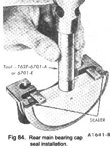
19. Position the seal forming tool as shown in Fig. 84 and complete the seal installation. After installation, cut the ends of the seal flush.
20. Apply a thin coating of oil-resistant sealer to the rear main bearing cap at the rear of the top mating surface (Fig. 84). Do not apply sealer to the area forward of the oil slinger groove. Install the rear main bearing cap and torque the cap bolts to specifications.
21. If the thrust bearing cap (No. 3 main bearing) has been removed, install it as follows:
Install the thrust bearing cap with the bolts finger-tight. Pry the crankshaft forward against the thrust
|
surface of the upper half of the bearing (Fig. 92). Hold the crankshaft forward and pry the thrust bearing cap to the rear (Fig. 92). This will align the thrust surfaces of both halves of the bearing. Retain the forward pressure on the crankshaft. Torque the cap bolts to specifications (Fig. 92).
22. Clean the oil pump inlet tube screen. Install the oil pump and the inlet tube assembly.
23. Position the oil pan gaskets on the oil pan. Position the oil pan front seal on the cylinder front cover. Position the oil pan rear seal on the rear main bearing cap. Install the oil pan and related parts. Install the oil level dipstick.
24. Fill the crankcase. Start the engine and check for oil pressure. Operate the engine at fast idle and check for oil leaks.
Connecting rod bearing
1. Follow steps 1 and 2 under Main Bearing Replace-ment
2. Turn the crankshaft until the connecting rod to which new bearings are to be fitted is down. Remove the connecting rod cap. Remove the bearing inserts from the rod and cap.
3. Be sure the bearing Inserts and the bearing bore in the connecting rod and cap are clean. Foreign material under the inserts may distort the bearing and cause a failure.
4. Clean the crankshaft journal. When replacing standard bearings with new bearings, it is good practice to first try to obtain the proper clearance with two blue bearing halves.
5. Install the bearing inserts in the connecting rod and cap with the tangs fitting in the slots provided.
6. Pull the connecting rod assembly down firmly on the crankshaft Journal.
7. Place a piece of Plastigage on the lower bearing surface, the full width of the cap and about 1/2 in. off-centre.
|
 **
**